
 NOTE: This material is intended to be written for people who want to know about the very basics of CATIA V5 while learning some Japanese terms. It is also intended to be read among Japanese CATIA specialists who want to study English.
The following is only an introduction, a very beginning to CATIA, so it might not be helpful if you are expecting any tips on CATIA when you operate it. But hopefully it might help someone wishing learn some specific terms in Japanese and English.
Here's the word list:

Here's the word list:

Creating geometries in CATIA V5 is to work in a workbench. Any 2D or 3D shape will be created in a workbench with various icon functions.
There are different functions in each workbench in order
to create a shape.
The major workbenches are:
1. Sketcher - スケッチャー
2. Part Design - パート・デザイン
3. GSD (Generative Shape Design) - ジェネレーティブ シェイプ・デザイン
4. Assembly Design - アセンブリ・デザイン
5. Drafting - ドラフティング
Specification tree (仕様ツリー):
Every action you have taken in CATIA will be logged on
the tree structure displayed on the screen. This is called the “specification tree”
(仕様ツリー) and it
looks like this:

Users will have to be conscious of this tree structure all the time because it will be important to know how the data was created. Visualizing the history like this allows a user or other users to modify the data when you need to.
If the specification tree is not managed well, you or other people will be in trouble the next time you are at it. You might have to say, “Where the heck do I have to get back?? I can’t modify it!!” - It is almost like when you don't keep your room organized, and go to school in the morning leaving your locker room key at home. You call your mom from school later but she can't find it. She says your room is messy; she has no idea where to find it. Both you and your mom might be upset and you would ruin the day. (This is what my daughter did about a year ago ….)
Users/companies are always thinking about reducing the time of work and cut the cost. Being organized here on this specification
tree is a very important factor to keep your modelling process more efficient and
productive.
Feature/
Element (フィーチャー/ 要素):
In many cases, a 3D geometry will be created from a 2D
sketch.
Let us create a geometry like this, for example.

This is how you create it:
1. Go
to the [Sketcher]
workbench.
2. Create
a [Profile]
like this in the
[Sketcher] workbench.

3. The
[Sketcher] workbench is intended to create 2D profiles only, so you will have
to go to another workbench to make it 3-dimensional. Press the [Exit] icon.
4. When
you exit the [Sketcher] workbench, you will be brought to either the
[Generative Shape Design] workbench or the [Part Design] workbench. They are
both capable of creating 3D geometries.
5. Let’s
suppose you are in the [Part Design] workbench now.

The specification tree will look like
this:
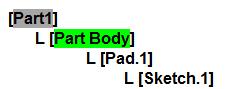
If you make a hole on this geometry, [Hole.1] will be added in the specification tree and it will also be called
a feature
(フィーチャー).
The specification tree, by the way, will be displayed
like this:

There is not much to distinguish with it but a feature (including
[Pad], [Hole], etc.) can also be called an element (要素).
Part/
Product (Assembly)
When multiple geometries will be created, they can be managed
& treated as 1 [Part] file, or
as 1 [Product] file (an assembly
file) with multiple [Part] files in
it.
[Example 1:]
If 2 geometries will be created and will be managed in 1 [Part] file, the specification tree
will be displayed like this:

[Example 2:]
If 2 geometries will be created and be managed in 1 [Product] file with multiple [Part] files, the specification tree
will be displayed like this:

[Example.1] and [Example.2] are two different things. They are more different than
how they look.
#1. [Example.1]
is 1 [Part] file, so only 1 file will be
created. Because it is 1 [Part] file,
it will be treated as if it were 1 single machine part, so even if there are
many [Bodies] or [features] in it with multiple geometries, constraints
(e.g. fixing,
positioning with coincidence/
offset, or contacting) will not be applied in order to define relationships between one [Body] and other. But it is simpler
than a [Product] file to save and manage data, since it is 1 single file. The [Save As]
will be used to save data (just like MS Word or Power Point).
#2. [Example.2]
shows that there is 1 [Product] file as the dominant product with 2 [Part] files under it. This means that 3 files (1 [Product] file and 2 [Part] files) will be created and will have to be managed. This sounds like bad news because you have to keep as many as 3 files instead of 1. - The good news, however, is that constraints (e.g. fixing, positioning with coincidence/ offset, or contacting) can be applied to these [Part] files in order to define relationships between one [Part] and other, so they will be
treated like separate parts.
For this reason, 1 [Part]
file can be re-used independently if it is saved somewhere you determined. This
way, you will be able to keep multiple [Part]
files out there in order to manage them, and you may want to call it a parts catalog.
The [Save As] command will not be
used here because each file ([Product], [Part]) has to be saved with the save
directory you will define respectively.
A [Product] structure (an assembly modelling) enables to be developed to kinematics (simple machanisms analysis).
Select the [Save Management] command to display the list of files that are open. In this example, the [Product] data contains 1 [Product] file and 2 [Part] files. Make sure that each file will need to have some items to be defined, such as a file name titled as [Name] and save directory titled as [Location].
